OKEP-5224: Connecting UserDefinedNetworks
Problem Statement
A (C)UDN is an isolated island, however, we have users that wish to connect these islands together for multiple reasons. This OKEP proposes a solution to connect multiple UserDefinedNetworks or ClusterUserDefinedNetworks together, better known as "Connecting (C)UDNs". This solution will ensure that (C)UDNs remain isolated unless an explicit request to connect them together has been made.
User Personas:
Admin: Cluster administrator who has the highest priviledge access to the cluster. Admin creates the namespaces for each tenant in the cluster.Tenant: A tenant is an end user who owns the resources (workloads, policies, services, udns) created in one or more namespaces that are designated to them by admins. They cannot update or mutate the namespace(s) but they live within the namespace(s) boundary controlled using RBAC.
Goals
- Connecting and disconnecting UDNs and CUDNs within the same cluster aka intra-cluster-udn-connectivity for admins (can be done as day0 or day2).
- Support for connecting primary
CUDN<->UDNacross namespaces[footnote] which includes:- Support for connecting
CUDN<-> CUDN(forAdminrole only) - Support for connecting
CUDN<->UDN(forAdminrole only) - Support for connecting
UDN<->UDN(forAdminrole only)
- Support for connecting
- Support for connecting
Layer3<->Layer3,Layer2<->Layer2andLayer3<->Layer2type networks. - Support for only
role:Primarytype CUDN, and UDN connections. - Support for pods, services (clusterIPs only since expectation today is that NodePorts and LoadBalancer type services are already exposed externally and hence reachable across UDNs) and network policies across the connected UDNs and CUDNs.
- Ensure the proposed API is expandable for also connecting and disconnecting UDNs or CUDNs across clusters in the future if need be.
[footnote] Food for thought: Currently, there is no need to consider connecting UDNs within the same namespace since there is no support for more than 1 primary-UDN in a namespace and each pod would have connection to its primary and secondary UDNs in its namespace. However there are use cases for connecting secondary UDNs within a namespace to consider in the future. There is also a future enhancement on multiple primary UDNs which if accepted can automatically leverage the work happening in this enhancement.
Future Goals
- [Tenant usecase] Connecting and disconnecting UDNs owned by the same tenant in same namespace or across different namespaces they own, in a self-serve fashion without any admin intervention. A tenant should be able to connnect the secondary networks that belong to them. This would most likely be a namespace-scoped API.
- Tenants being able to request for interconnecting their networks
with other tenants.
- We need to understand exact use cases for why we need tenants to initiate connection requests with other tenants. How will a tenant know other tenants that exist on the cluster? In cases like finance tenant wanting to use IT tenant's services, they could open a ticket to the admin to make that happen.
- Regardless, the tenant API might need more RBAC considerations if we get such use cases
- One other idea is to re-use the same peering semantics that network policies API uses where both the CRs across both the tenant namespaces would need to select each other to be permitted connectivity
- Admins being able to connect
role:SecondaryUDNs and CUDNs. The reason why this is a future goal is because of the following reasons:- For UDNs, given
SecondaryUserDefinedNetworkSelectoruses a combination of namespace selector and network selector, a tenant could change the labels on the UDN thereby causing security issues. Hence this type of selector support will come later where we might want to add a well-known label to be able to leverage selectors. - The secondary networks don't have the same level of topology parity
as primary networks today. So there is no support for transit router
or egress gateway today in
Layer2secondary networks. Hence we would need to add the transit router to the secondary networkLayer2topology as well which can come in the future.Layer3networks don't have the same issue as the required topology parity exists but given we'd need that change forLayer2might as well do the full secondary networks connect support in future.
- For UDNs, given
- Connecting two UDNs with overlapping subnets won't be supported in the first phase. This is a valid use case scenario but harder to implement.
Non-Goals
- Support for selecting NADs directly. Since UDNs is the future, new features should not be added on NADs.
- Support for this feature in non-interconnect architecture is out of scope since we plan to deprecate non-interconnect mode soon.
- Support for
localnettype network connections is out of scope. localnettype networks can be connected together using bridges alreadylocalnet<->layer2orlocalnet<->layer3will not be covered here.- Supporting Live Migration and PersistentIPs across connected UDNs.
- Connecting and disconnecting UDNs and CUDNs across two clusters aka inter-cluster-udn-connectivity for admins (can be done as day0 or day2). The plan is to be able to do this using EVPN protocol. See enhancement on EVPN to see how it is planned to be leveraged as the mode to connect different UDNs across clusters. But regardless, the API bits around how to request connectivity needs more fleshing and EVPN's primary use case is not about connecting UDNs across clusters.
Introduction
OVN-Kubernetes supports two types of user-defined networks for workload isolation:
-
UserDefinedNetworks (UDNs): Namespace-scoped networks that tenants can create to isolate workloads within a namespace.
-
ClusterUserDefinedNetworks (CUDNs): Cluster-scoped networks that admins can use to connect multiple namespaces as part of the same isolated network.
These networks can be configured with different roles:
-
role:Primary: The network becomes the primary network for workloads. Workloads attached to a primary UDN/CUDN cannot communicate with workloads on other UDNs/CUDNs or the default network. -
role:Secondary: Enables multihoming scenarios, allowing pods to be attached to multiple networks simultaneously.
Currently, workloads on different (C)UDNs are completely isolated from each other. However, there are scenarios where partial or full connectivity between microservices segmented across different (C)UDNs is desirable (see use cases section).
This OKEP defines how to implement connectivity between two or more (C)UDNs within a single cluster. The following sections outline the design assumptions and implementation details.
Symmetric nature of UDN Connectivity
If UDN-A is connected to UDN-B then that means UDN-B is connected to UDN-A. When connecting those networks together it assumes bi-directional relationship.
Non-Transitive nature of UDN Connectivity
If UDN-A and UDN-B are connected together and UDN-B and UDN-C are connected together, that does not mean UDN-A is connected to UDN-C. Reasoning is we cannot assume something indirectly - It's always best to let the user express what they'd like to see connected.
User-Stories/Use-Cases
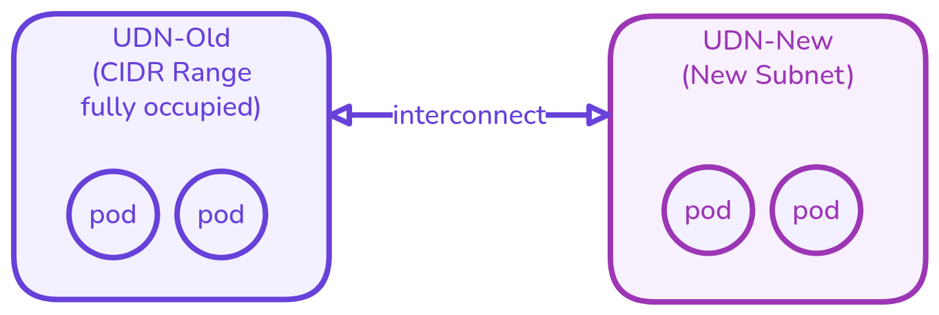
Story 1: Allowing network expansion for a tenant
As a cluster admin, I want to connect my newly created UDN-New with an existing UDN-Old so that they can communicate with each other as if being part of the same network.
Example: Existing (C)UDN has full occupancy of its address-space and we don’t allow CIDR expansion or mutation of UDN Spec today.
The admin created UDN-Old with a defined subnet CIDR range which gets exhausted on a 500th day, now the admin cannot mutate UDN-Old to change or expand its subnet CIDR range. Admin creates a new UDN-New (could be in a totally different cluster) and now wants to interconnect them together.
Story 2: Allowing connectivity between two tenants through exposed clusterIP services
As a cluster admin, I want to allow tenant-Green to be able to access the clusterIP microservice exposed by tenant-Blue without direct access to workloads behind the service.
Example: When separate services owned by different teams need to communicate via APIs like frontend needing to access database through the backend service.
The admin created UDN-Blue and UDN-Green that were isolated initially but now wants to allow partial inter-tenant communication. Say data produced by microservice blue needs to be consumed by microservice green to do its task.
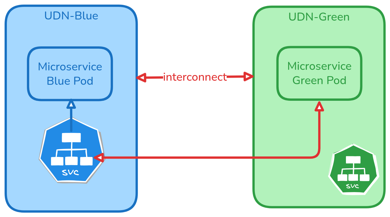
When the two networks have overlapping subnets, using service clusterIP as a way to allow communication is valid use case.
Story 3: Allowing connectivity between two networks with overlapping subnets through exposed clusterIP services
As a cluster admin, I want to allow tenant-Green to be able to access the clusterIP microservice exposed by tenant-Blue even though tenant-Green and tenant-Blue have overlapping pod subnets.
Example: IPAddress Management is hard. It is not possible to predict the future of how all applications will communicate with one another. There is a chance app-type-green and app-type-blue got the same pod subnets and now they need to talk to each other. While allowing direct connection of the two overlapping pod subnet networks is hard, a middleground is to use clusterIPs to communicate.
Story 4: Merging two tenants (maybe even temporarily)
As a cluster admin, I want to now connect my existing UDN-Blue and UDN-Green so that they can communicate with each other as if being part of the same network.
Example: The admin created UDN-Blue and UDN-Green that were isolated initially but now wants to treat them as being part of the same network. Pods cannot be rewired given they are part of two different UDNs. Say when different teams within the same organization operate as separate tenants but collaborate on a project requiring unrestricted communication for a period of time and then want to disconnect from each other later.
Story 5: Same UDN across multiple clusters must be connected by default
As a cluster admin, I want to connect my workloads which are part of the same UDN but are in different clusters.
Example: The user has split their workloads into multiple clusters thereby the same UDN could be fragmented across different clusters. These pods should be able to communicate with each like it would be if they were on the same cluster but be isolated from other workloads.
NOTE: Cross cluster UDN connecting is not targeted in this OKEP, but is covered here since connecting UDNs within the cluster is the first step here.
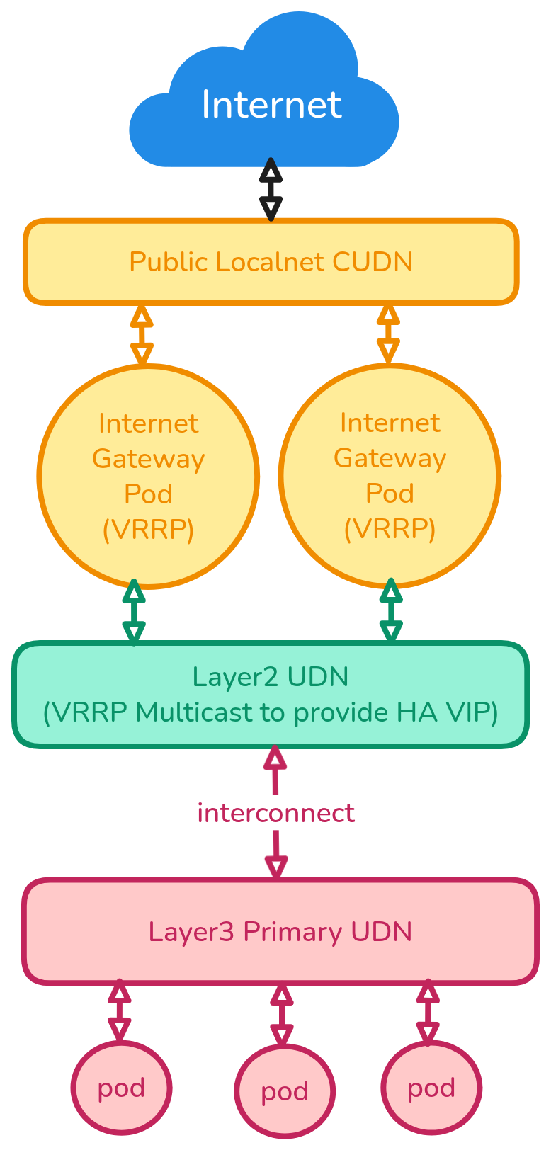
Story 6: Connecting mixed type networks together (Layer2 Network workloads with Layer3 Primary/Default Network)
As a cluster admin, I manage isolated tenants (a bunch of interconnected pods) and share them with my users. Every tenant has its own Primary Layer3 UDN to emulate its own cluster network, but isolate it from the other tenants. Northbound/internet traffic from my tenants is always flowing through additional gateways that I manage. Gateways require HA support, which is done using OVN virtual Port type, which is only supported when all parent ports are located on the same switch, hence the UDN used by the Gateways is Layer2 (Primary).
To make tenants' traffic flow through the gateways, I need to interconnect Primary Layer3 network with Primary Layer2 network. Here is a diagram illustrating this ask:
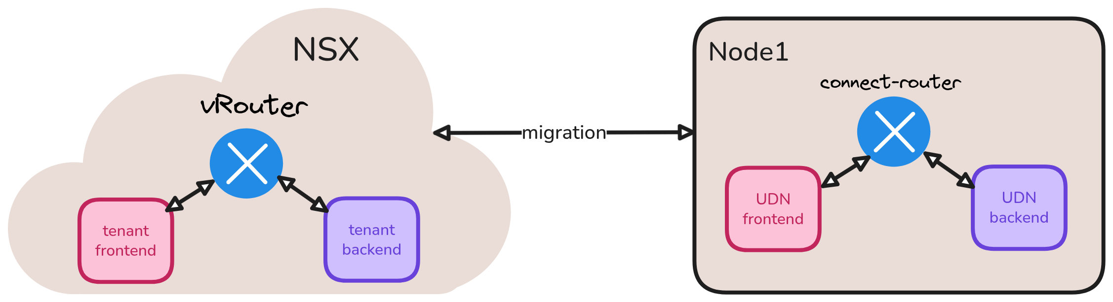
Story 7: Migration of connected tenant workloads from other platforms like NSX into OVN-Kubernetes
As a cluster admin, I manage isolated tenants on my native NSX platform where they are already seggregated into segments using networks. Some of these segments are connected through vRouter for mutual access. I want to migrate such workloads into OVN-Kubernetes platform by leveraging user defined networks. I would need connecting UDNs feature to replicate that same workload architecture. The alternative of placing those workloads into same UDN and using network policies will not work because it is significant architectural change we would need to mandate on each tenant since tenant own their networks.
Example: Tenant-frontend has access to Tenant-backend's databaseAPI workloads on NSX through vRouter, I want to migrate both these tenants into OVN-Kubernetes platform keeping that architecture intact.
Story 8: [Future Use Case] Tenant self-connection without admin intervention
As a tenant owner, I want to connect my workloads which are part of two different namespaces (networks) in the same cluster with no admin intervention.
Example: If the same tenant owns microservices across 5 namespaces that are 5 different networks, there should be provision for this tenant to connect their networks together without the requirement for an admin to intervene. The reason could be the same as the above admin user stories but this story captures the tenant intent with no admin intervention
Proposed Solution
This section tries to answer: How can an admin declare two (C)UDNs to be connected?
Config for enabling the feature
The whole feature will be behind a config flag called
--enable-network-connect which has to be set to true to get this
feature.
API Details
This enhancement proposes a new CRD to allow admins to request multiple networks to be connected together.
ClusterNetworkConnect CR will be cluster-scoped resource and admin-only
API that will allow admins to select multiple different networks that
need to be connected together. It will also allow specifying what level
of connectivity is expected. See the API definitions for more details.
Admins can create a ClusterNetworkConnect CR which signals the
controller to connect the topologies of the UDNs selected by this CR.
Sample YAML:
apiVersion: k8s.ovn.org/v1
kind: ClusterNetworkConnect
metadata:
  name: colored-enterprise
spec:
  networkSelectors: # can match on UDNs and/or CUDNs
    - networkSelectionType: ClusterUserDefinedNetworks
      clusterUserDefinedNetworkSelector:
        networkSelector:
          matchExpressions:
          - key: kubernetes.io/metadata.name
            operator: In
            values:
            - blue-network
            - green-network
    - networkSelectionType: PrimaryUserDefinedNetworks
      primaryUserDefinedNetworkSelector:
        namespaceSelector:
          matchExpressions:
          - key: kubernetes.io/metadata.name
            operator: In
            values:
            - yellow
            - red
  connectSubnets: # can have at most 1 CIDR for each family type
  - cidr: "192.168.0.0/16"  # 65K total IPs
    networkPrefix: 24 # 255 IPs per layer3 network = ~100 possible nodes in your cluster
  - cidr: "fd01::/64"
    networkPrefix: 96
  connectivity:
    - PodNetwork
    - ServiceNetwork
connectivity field will ensure we can add support for enabling
more types of features for the connected UDNs granularly in the future.
At least one of these options must be set and validations will be added
for which combinations of these options could/should be set together
* If PodNetwork is enabled then admin is asking for full
pod2pod connectivity across UDNs
* If ServiceNetwork is enabled then admin is asking for
clusterIPs to be reachable across UDNs.
* If this flag is set but PodNetwork is not set, then
it means users only want partial connectivity through services and
not full mesh pod connectivity.
* connectSubnets field is used to take a configurable subnet from the end
user that will be used to connect the different networks together. The
slice needs to be big enough to accommodate an IP per network per node
for layer3 network connectivity. So if there are M nodes in your cluster
and N_L3 networks you should have 2*(N_L3×M) IPs for allocation in this slice.
The networkPrefix contains the prefix length allocated for each
connected layer3 network. From this pool each node get's a /31 or /127 point to
point network for actual topology connectivity.
To connect layer2 networks we don't need per node-network slices, we just
need one /31 or 127 slice per network.
ConnectSubnets value is expected to be configured uniquely across multiple ClusterNetworkConnect
CRs that select the same network i.e. If a given network is selected as part
of more than 1 ClusterNetworkConnect API, each of those ClusterNetworkConnect
APIs must have a unique connect subnet. If a user accidentally configures overlapping values,
we must have a status check to block and report this in the status. See
status validation section for more details.
ConnectSubnets field cannot be mutated to keep things simple in the first
iteration/implementation of this enhancement. Can be revisited in future.
API field details and CEL Validations
API fields are described in detail below along with field validations:
// ClusterNetworkConnect enables connecting multiple User Defined Networks
// or Cluster User Defined Networks together.
//
// +genclient
// +genclient:nonNamespaced
// +k8s:openapi-gen=true
// +k8s:deepcopy-gen:interfaces=k8s.io/apimachinery/pkg/runtime.Object
// +kubebuilder:resource:path=clusternetworkconnects,scope=Cluster,shortName=cnc,singular=clusternetworkconnect
// +kubebuilder:object:root=true
// +kubebuilder:subresource:status
// +kubebuilder:printcolumn:name="Age",type="date",JSONPath=".metadata.creationTimestamp"
// +kubebuilder:printcolumn:name="Status",type=string,JSONPath=".status.status"
type ClusterNetworkConnect struct {
    metav1.TypeMeta   `json:",inline"`
    metav1.ObjectMeta `json:"metadata,omitempty"`

    // +kubebuilder:validation:Required
    // +required
    Spec ClusterNetworkConnectSpec `json:"spec"`

    // +optional
    Status ClusterNetworkConnectStatus `json:"status,omitempty"`
}

// ClusterNetworkConnectSpec defines the desired state of ClusterNetworkConnect.
// +kubebuilder:validation:XValidation:rule="!self.networkSelectors.exists(i, i.networkSelectionType != 'ClusterUserDefinedNetworks' && i.networkSelectionType != 'PrimaryUserDefinedNetworks')",message="Only ClusterUserDefinedNetworks or PrimaryUserDefinedNetworks can be selected"
type ClusterNetworkConnectSpec struct {
    // networkSelectors selects the networks to be connected together.
    // This can match User Defined Networks (UDNs) and/or Cluster User Defined Networks (CUDNs).
    // Only ClusterUserDefinedNetworkSelector and PrimaryUserDefinedNetworkSelector can be selected.
    //
    // +kubebuilder:validation:Required
    // +required
    NetworkSelectors types.NetworkSelectors `json:"networkSelectors"`

    // connectSubnets specifies the subnets used for interconnecting the selected networks.
    // This creates a shared subnet space that connected networks can use to communicate.
    // Can have at most 1 CIDR for each IP family (IPv4 and IPv6).
    // Must not overlap with:
    //  any of the pod subnets used by the selected networks.
    //  any of the transit subnets used by the selected networks.
    //  any of the service CIDR range used in the cluster.
    //  any of the join subnet of the selected networks to be connected.
    //  any of the masquerade subnet range used in the cluster.
    //  any of the node subnets for choosen by the platform.
    //  any of other connect subnets for other ClusterNetworkConnects that might be selecting same networks.
    //
    // Does not have a default value for the above reason so
    // that user takes care in setting non-overlapping subnets.
    // Cannot be mutated once set.
    // +kubebuilder:validation:Required
    // +kubebuilder:validation:MinItems=1
    // +kubebuilder:validation:MaxItems=2
    // +kubebuilder:validation:XValidation:rule="self == oldSelf", message="connectSubnets is immutable"
    // +required
    // +kubebuilder:validation:XValidation:rule="size(self) != 2 || !isCIDR(self[0].cidr) || !isCIDR(self[1].cidr) || cidr(self[0].cidr).ip().family() != cidr(self[1].cidr).ip().family()", message="When 2 CIDRs are set, they must be from different IP families"
    ConnectSubnets []ConnectSubnet `json:"connectSubnets"`

    // connectivity specifies which connectivity types should be enabled for the connected networks.
    //
    // +kubebuilder:validation:Required
    // +kubebuilder:validation:MinItems=1
    // +kubebuilder:validation:MaxItems=2
    // +kubebuilder:validation:XValidation:rule="self.all(x, self.exists_one(y, x == y))",message="connectivity cannot contain duplicate values"
    connectivity []ConnectivityType `json:"connectivity"`
}

// +kubebuilder:validation:XValidation:rule="isCIDR(self) && cidr(self) == cidr(self).masked()", message="CIDR must be a valid network address"
// +kubebuilder:validation:MaxLength=43
type CIDR string

// +kubebuilder:validation:XValidation:rule="!has(self.networkPrefix) || !isCIDR(self.cidr) || self.networkPrefix > cidr(self.cidr).prefixLength()", message="networkPrefix must be smaller than CIDR subnet"
// +kubebuilder:validation:XValidation:rule="!has(self.networkPrefix) || !isCIDR(self.cidr) || (cidr(self.cidr).ip().family() != 4 || self.networkPrefix < 32)", message="networkPrefix must < 32 for ipv4 CIDR"
type ConnectSubnet struct {
  // CIDR specifies ConnectSubnet, which is split into smaller subnets for every connected network.
  // This CIDR should be containing 2*((Number of L3 networks*Max Number of Nodes)+Number of L2 networks) IPs.
  // Example: cidr= "192.168.0.0/16", networkPrefix= 24 means that you can connect 256 Layer3 networks OR
  // 255 Layer3 networks and 128 Layer2 networks
  //
  // CIDR also restricts the maximum number of networks that can be connected together
  // based on what CIDR range is picked. So choosing a large enough CIDR for future use cases
  // is important.
  // +required
  CIDR CIDR `json:"cidr"`

  // networkPrefix specifies the prefix length for every connected network.
  // This prefix length should be equal to or longer than the length of the CIDR prefix.
  //
  // For example, if the CIDR is 10.0.0.0/8 and the networkPrefix is 24,
  // then the connect subnet for each connected layer3 network will be 10.0.0.0/24, 10.0.1.0/24, 10.0.2.0/24 etc.
  // For each connected layer2 network we will allocate a /networkPrefix range
  // that is then used to allocate /31 and /127 slices for each layer2 network.
  // A good practice is to set this to a value that ensures it contains more
  // than twice the number of maximum nodes planned to be deployed in the cluster
  // and how frequently nodes are created and destroyed.
  // To be safe, better to set this to a value that's 4 times the maximum nodes planned
  // to be deployed in the cluster.
  // Example - required values;
  // if you plan to deploy 10 nodes, minimum required networkPrefix is /27 (20+ IPs)
  // if you plan to deploy 100 nodes, minimum required networkPrefix is /24 (200+ IPs)
  // if you plan to deploy 1000 nodes, minimum required networkPrefix is /21 (2000+ IPs)
  // if you plan to deploy 5000 nodes, minimum required networkPrefix is /18 (10000+ IPs)
  //
  // However to be safe and in case nodes are created and destroyed at fast rate,
  // set it to 4 times max nodes of the cluster:
  // if you plan to deploy 10 nodes, set the networkPrefix to /26 (40+ IPs)
  // if you plan to deploy 100 nodes, set the networkPrefix to /23 (400+ IPs)
  // if you plan to deploy 1000 nodes, set the networkPrefix to /20 (4000+ IPs)
  // if you plan to deploy 5000 nodes, set the networkPrefix to /17 (20000+ IPs)
  // This field restricts the maximum number of nodes that can be deployed in the cluster
  // and hence its good to plan this value carefully along with the CIDR.
  //
  // +kubebuilder:validation:Minimum=1
  // +kubebuilder:validation:Maximum=127
  // +required
  NetworkPrefix int32 `json:"networkPrefix"`
}

// ConnectivityType represents the different connectivity types that can be enabled for connected networks.
// +kubebuilder:validation:Enum=PodNetwork;ServiceNetwork
type ConnectivityType string

const (
    // PodNetwork enables direct pod-to-pod communication across connected networks.
    PodNetwork ConnectivityType = "PodNetwork"

    // ServiceNetwork enables ClusterIP service access across connected networks.
    // Note that services of type nodeports and loadbalancers are already reachable
      // across networks by default.
    ServiceNetwork ConnectivityType = "ServiceNetwork"
)

// StatusType represents the status of a ClusterNetworkConnect.
// +kubebuilder:validation:Enum=Success;Failure
type StatusType string

const (
    // Success indicates that the ClusterNetworkConnect has been successfully applied.
    Success StatusType = "Success"

    // Failure indicates that the ClusterNetworkConnect has failed to be applied.
    Failure StatusType = "Failure"
)

// ClusterNetworkConnectStatus defines the observed state of ClusterNetworkConnect.
type ClusterNetworkConnectStatus struct {
    // status is a concise indication of whether the ClusterNetworkConnect
    // resource is applied with success.
    // +kubebuilder:validation:Optional
    Status StatusType `json:"status,omitempty"`

    // conditions is an array of condition objects indicating details about
    // status of ClusterNetworkConnect object.
    // +patchMergeKey=type
    // +patchStrategy=merge
    // +listType=map
    // +listMapKey=type
    Conditions []metav1.Condition `json:"conditions,omitempty"`
}

// ClusterNetworkConnectList contains a list of ClusterNetworkConnect.
// +kubebuilder:object:root=true
// +k8s:deepcopy-gen:interfaces=k8s.io/apimachinery/pkg/runtime.Object
type ClusterNetworkConnectList struct {
    metav1.TypeMeta `json:",inline"`
    metav1.ListMeta `json:"metadata,omitempty"`
    Items           []ClusterNetworkConnect `json:"items"`
}
Validation Field Checks
In the implementation, after parsing the ClusterNetworkConnect
object, we must ensure the following:
connectSubnetsmust not conflict with: 1) pod subnets of the selected networks to be connected 2) transit subnets of the selected networks to be connected 3) service CIDR range used in the cluster 4) join subnet of the selected networks to be connected 5) masquerade subnet range used in the cluster 6) node subnets for choosen by the platform. This is the responsibility of the user and we won't provide validation for node subnets since fetching that value could vary from platform to platform. We will cover this in the docs. If it does, we need to provide validation and feedback to the end user for the conflict.- Since connection of overlapping pod subnet networks is not allowed in first phase, we must detect the collision and report the error back to the user via the status
- Expectation is for users to initiate the connection of networks of same family types together. If a singlestack IPV6 UDN is tried to be connected to singlestack IPV4 UDN, then we will have to validate this as a misconfiguration and have a status error for this.
Valid ways of Connecting/Selecting/Disconnecting UDNs
- A network could be selected as part of more than one network connnect, so
what is the expectation when two Connect APIs are designed that select the
exact same set of networks? How do we control validation of such scenarios?
Example, ClusterNetworkConnect-A selects blue and green networks and
ClusterNetworkConnect-B selects blue and red networks:
- In such scenarios the same network's router is going to be connected to
more than one
connect-router. So blue network will be connected to bothconnect-router-Aandconnect-router-B. - However given non-transitive relation and absence of connecting routes, indirect connection of green and red will not happen.
- We must add validation in code to ensure if more than 1
ClusterNetworkConnect API selects the same network, then they must
have non-overlapping
connectSubnetsfield configured. If there is a conflict, we must emit an event on the connectAPI and fail to create the plumbing for the subsequent case. OVN does not handle blocking the creation of two ports on the same router with same subnets. So if that happens, it will cause wrong routing and hence OVN-Kubernetes must detect this conflict.
- In such scenarios the same network's router is going to be connected to
more than one
- A ClusterNetworkConnect could be selecting a subset of networks already selected by
another ClusterNetworkConnect API. What is the expectation in this case?
Example,
ClusterNetworkConnect-A selects blue, green, red and yellow networks and
ClusterNetworkConnect-B selects blue and green networks.
- This is going to be considered a user-configuration error oversight.
This same issue also exists for other APIs like
RouteAdvertisement(wonder what we do there?). - We expect the rules to be additively implemented but in this case, we won't optimize for anything since its a hard problem to solve. We will end up create duplicate connect networks unnecessarily and it will be an ECMP routing situation on which connect network will be used to reach the other side.
- We will not provide any validation around selectors across all connect
APIs to rule out overlap except we will ensure the
connectSubnetsis non-overlapping across all connectAPIs that select a given network which is same as the first case.
- This is going to be considered a user-configuration error oversight.
This same issue also exists for other APIs like
- Selecting a network can be done as a day0 or day2 operation. So label changes to existing networks, new networks added and deleted need to be watched in order to connect and disconnect networks on the fly based on user configuration changes.
StatusConditions
The ClusterNetworkConnect status will include a status field
with a concise indication and a conditions array with detailed
condition objects. The controller will update these conditions based
on validation results.
Condition Types
- The
Acceptedtype condition will be done from the cluster-manager which indicates whether the validation checks passed. - The
Ready-In-Zone-<nodename>type condition will be done from each node's ovnkube-controller which indicates if all the corresponding OVN objects were created correctly. - Based on whether
statusof the above two types of conditions isTrueorFalse, the final stringstatuswill be markedSuccessorFailure
Valid Scenario
When a ClusterNetworkConnect resource is successfully applied,
the following conditions indicate healthy states:
status:
  status: "Success"
  conditions:
  - type: "Accepted"
    status: "True"
    reason: "ValidationSucceeded"
    message: "All validation checks passed successfully"
    lastTransitionTime: "2023-10-01T09:59:00Z"
  - type: "Ready-In-Zone-ovn-worker"
    status: "True"
    reason: "OVNSetupSucceeded"
    message: "Connect router and all ports created successfully"
    lastTransitionTime: "2023-10-01T10:00:00Z"
  - type: "Ready-In-Zone-ovn-worker2"
    status: "True"
    reason: "OVNSetupSucceeded"
    message: "Connect router and all ports created successfully"
    lastTransitionTime: "2023-10-01T10:00:00Z"
Invalid Scenarios
When validation fails or errors occur, the following error conditions will be reported:
Cluster-Manager Validation Errors:
status:
  status: "Failure"
  conditions:
  - type: "Accepted"
    status: "False"
    reason: "ConnectSubnetExhausted"
    message: "Insufficient IP addresses in connect subnet 192.168.0.0/16.
    lastTransitionTime: "2023-10-01T10:00:00Z"
status:
  status: "Failure"
  conditions:
  - type: "Accepted"
    status: "False"
    reason: "OverlappingNetworkSubnets"
    message: "Cannot connect networks 'blue-network' and 'green-network': overlapping
    pod subnets 10.1.0.0/16 detected."
    lastTransitionTime: "2023-10-01T10:00:00Z"
status:
  status: "Failure"
  conditions:
  - type: "Accepted"
    status: "False"
    reason: "ConnectSubnetConflict"
    message: "Connect subnet 192.168.0.0/16 conflicts with pod subnet 192.168.1.0/24
    of network 'blue-network'"
    lastTransitionTime: "2023-10-01T10:00:00Z"
status:
  status: "Failure"
  conditions:
  - type: "Accepted"
    status: "False"
    reason: "ConnectSubnetOverlap"
    message: "Connect subnet 192.168.0.0/16 overlaps with ClusterNetworkConnect
    'enterprise-connect' which also selects network 'blue-network'.
    Each ClusterNetworkConnect selecting the same network must use non-overlapping
    connect subnets"
    lastTransitionTime: "2023-10-01T10:00:00Z"
status:
  status: "Failure"
  conditions:
  - type: "Accepted"
    status: "False"
    reason: "IPFamilyMismatch"
    message: "Cannot connect single-stack IPv4 network 'ipv4-network' with
    single-stack IPv6 network 'ipv6-network'. Networks must use the same IP family"
    lastTransitionTime: "2023-10-01T10:00:00Z"
status:
  status: "Failure"
  conditions:
  - type: "Accepted"
    status: "False"
    reason: "InsufficientNetworks"
    message: "Only 1 network selected, minimum 2 networks required for connection"
    lastTransitionTime: "2023-10-01T10:00:00Z"
status:
  status: "Failure"
  conditions:
  - type: "Accepted"
    status: "False"
    reason: "UnsupportedNetworkType"
    message: "Network 'blue-network' has role 'Secondary'. Only 'Primary' role networks are supported"
    lastTransitionTime: "2023-10-01T10:00:00Z"
status:
  status: "Failure"
  conditions:
  - type: "Accepted"
    status: "False"
    reason: "UnsupportedNetworkType"
    message: "Network 'localnet-network' has type 'localnet'. Localnet networks are not supported"
    lastTransitionTime: "2023-10-01T10:00:00Z"
status:
  status: "Failure"
  conditions:
  - type: "Accepted"
    status: "False"
    reason: "UnsupportedNetworkType"
    message: "Network connect feature is not supported when overlay tunneling is disabled"
    lastTransitionTime: "2023-10-01T10:00:00Z"
OVN Setup Failures: (Per Zone)
status:
  status: "Failure"
  conditions:
  - type: "Accepted"
    status: "True"
    reason: "ValidationSucceeded"
    message: "All validation checks passed successfully"
    lastTransitionTime: "2023-10-01T09:59:00Z"
  - type: "Ready-In-Zone-ovn-worker"
    status: "False"
    reason: "OVNSetupFailed"
    message: "Failed to create connect router ports: tunnel key allocation failed"
    lastTransitionTime: "2023-10-01T10:00:00Z"
  - type: "Ready-In-Zone-ovn-worker2"
    status: "False"
    reason: "OVNSetupFailed"
    message: "Failed to install routing policies for network 'blue-network'"
    lastTransitionTime: "2023-10-01T10:00:00Z"
Accepted Condition Reasons (from cluster-manager):
ValidationSucceeded- All validation checks passed successfullyConnectSubnetExhausted- Not enough IPs in connect subnet for all network-node combinationsOverlappingNetworkSubnets- Selected networks have overlapping pod subnets (not supported)ConnectSubnetConflict- Connect subnet conflicts with existing network subnets, service CIDR, etc.ConnectSubnetOverlap- Connect subnet overlaps with another ClusterNetworkConnect selecting the same networkIPFamilyMismatch- Attempting to connect networks with different IP familiesInsufficientNetworks- Less than 2 networks selected for connectionUnsupportedNetworkType- Network has unsupported role (Secondary) or type (localnet) or no-overlay mode enabled
Ready-In-Zone Condition Reasons (from ovnkube-controller):
OVNSetupSucceeded- OVN topology setup completed successfullyOVNSetupFailed- OVN topology setup failed
NOTE: The actual messages and name types may vary in implementation subject to reviews. These snippets only represent some potential examples.
Implementation Details
The implementation details of the feature are covered in various sub sections below:
Network Topology
This section covers the topology changes that will be introduced to connect networks together. NOTE: Besides the finalized proposal we have below for the topology change, there were other ideas which were discarded and listed in the alternatives section.
Connecting Layer3 type networks together
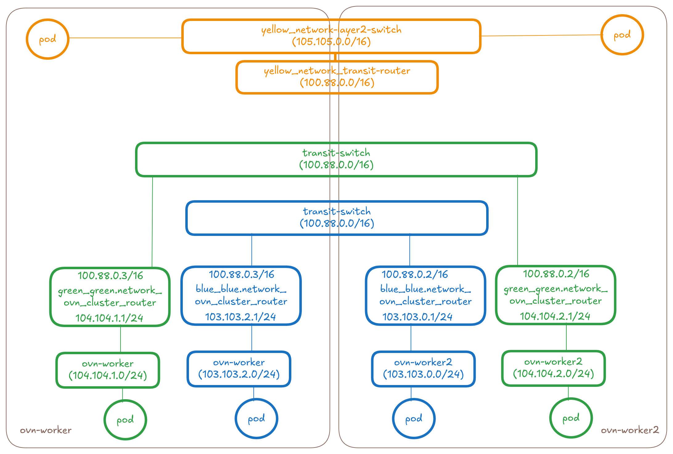
The below diagram shows the overlay part of the OVN Topology that OVN-Kubernetes creates for 3 UDN networks (blue, green and yellow) across two nodes.
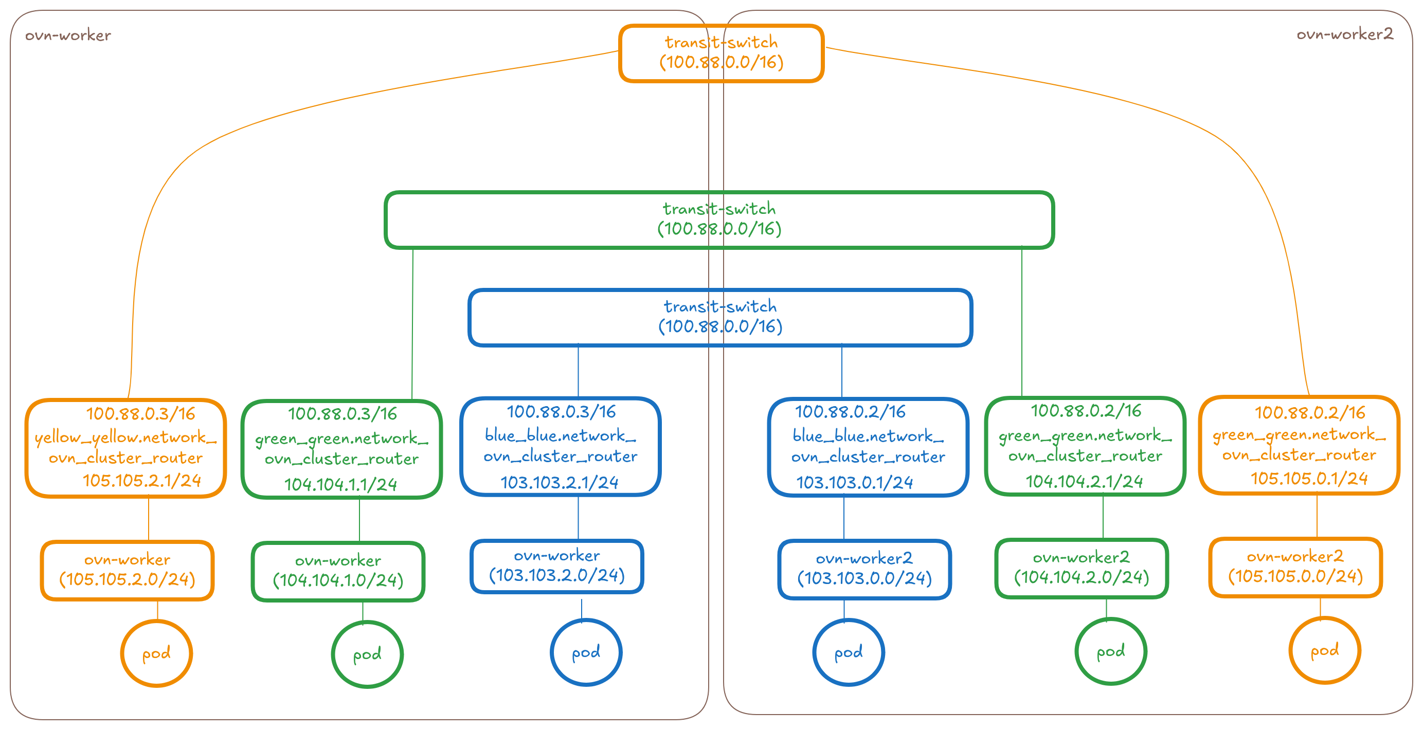
Let's take a look at how we can connect a blue network, green network and yellow network at the OVN layer.
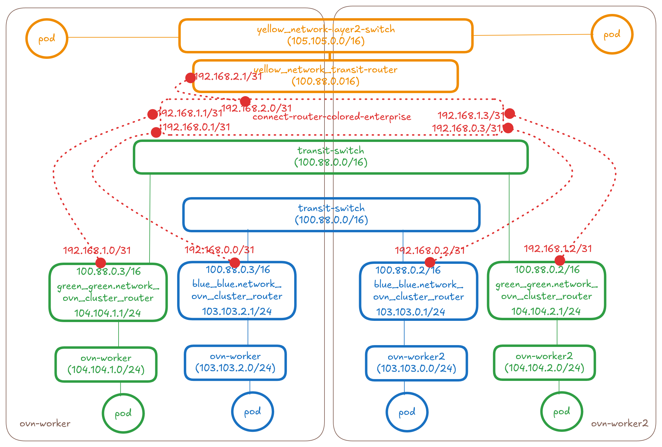
Add a new transit router between the ovn_cluster_routers of the networks
When the ClusterNetworkConnect CR gets created selecting these three
networks, the controller will make the following changes to the topology:
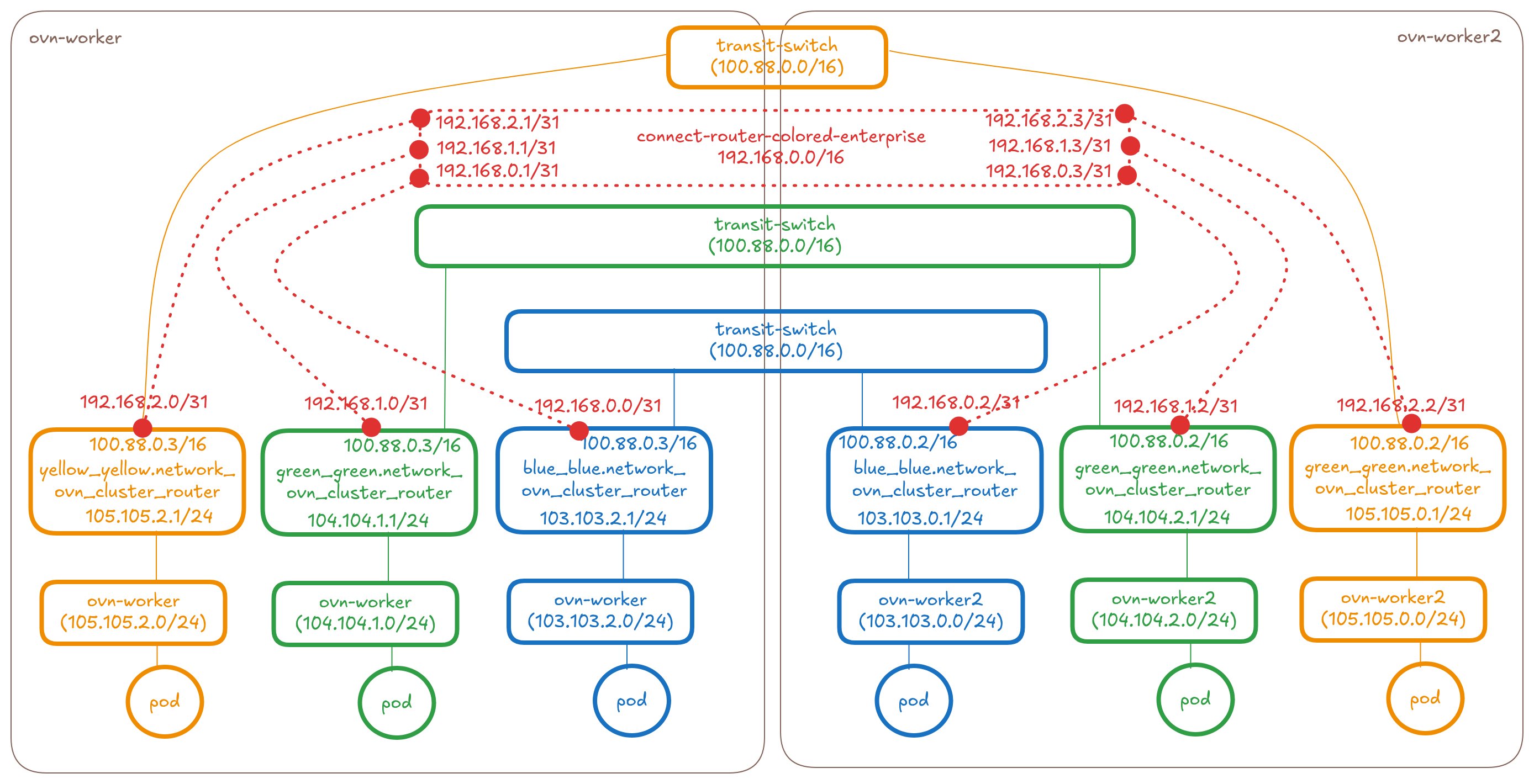
* Create a distributed connect-router-colored-enterprise (basically
a transit-router type in OVN used for interconnection)
* Connect the connect-router-colored-enterprise to the
ovn_cluster_router's of the blue, green and yellow networks on each
node using peer ports and tunnelkeys. We will have a total of N*M
links where N is the number of networks and M is the number of nodes.
* The port's will have IPs allocated from within the connectSubnets
value provided on the CR. For connecting N networks on M nodes we
would need 2×(N×M) IPs from the connectSubnets. See the controller
design section for more details.
So in this proposal it will be 1 new transit router per
ClusterNetworkConnect API.
NOTE: Please keep reading to the Pods and Services sections for
details around routes, policies and other OVN object changes.
In the OVN database of ovn-worker node, this new router looks like this:
sh-5.2# ovn-nbctl show connect-router-colored-enterprise
router bb053a19-99d5-4af8-a8e9-ebcab52908d8 (connect-router-colored-enterprise)
    port colored-enterprise-to-blue_blue-network-ovn-control-plane
        mac: "0a:58:c0:80:00:01"
        ipv6-lla: "fe80::858:c0ff:fe80:1"
        networks: ["192.168.0.1/31"]
    port colored-enterprise-to-yellow_yellow-network-ovn-control-plane
        mac: "0a:58:c0:80:00:03"
        ipv6-lla: "fe80::858:c0ff:fe80:3"
        networks: ["192.168.2.3/31"]
    port colored-enterprise-to-green_green-network-ovn-control-plane
        mac: "0a:58:c0:80:00:05"
        ipv6-lla: "fe80::858:c0ff:fe80:5"
        networks: ["192.168.1.5/31"]
    port colored-enterprise-to-green_green-network-ovn-worker2
        mac: "0a:58:c0:80:00:11"
        ipv6-lla: "fe80::858:c0ff:fe80:11"
        networks: ["192.168.1.17/31"]
    port colored-enterprise-to-blue_blue-network-ovn-worker
        mac: "0a:58:c0:80:00:07"
        ipv6-lla: "fe80::858:c0ff:fe80:7"
        networks: ["192.168.0.7/31"]
    port colored-enterprise-to-blue_blue-network-ovn-worker2
        mac: "0a:58:c0:80:00:0d"
        ipv6-lla: "fe80::858:c0ff:fe80:d"
        networks: ["192.168.0.13/31"]
    port colored-enterprise-to-yellow_yellow-network-ovn-worker2
        mac: "0a:58:c0:80:00:0f"
        ipv6-lla: "fe80::858:c0ff:fe80:f"
        networks: ["192.168.2.15/31"]
    port colored-enterprise-to-yellow_yellow-network-ovn-worker
        mac: "0a:58:c0:80:00:09"
        ipv6-lla: "fe80::858:c0ff:fe80:9"
        networks: ["192.168.2.9/31"]
    port colored-enterprise-to-green_green-network-ovn-worker
        mac: "0a:58:c0:80:00:0b"
        ipv6-lla: "fe80::858:c0ff:fe80:b"
        networks: ["192.168.1.11/31"]
The new ports added to the ovn_cluster_router's of the 3 networks:
sh-5.2# ovn-nbctl show yellow_yellow.network_ovn_cluster_router
router 01e9f2fc-e351-4c7a-a51a-ba5f2b2fb099 (yellow_yellow.network_ovn_cluster_router)
    port yellow_yellow-network-ovn-worker-to-colored-enterprise
        mac: "0a:58:c0:80:02:08"
        ipv6-lla: "fe80::858:c0ff:fe80:8"
        networks: ["192.168.2.8/31"]
---
_uuid               : c78b105c-d2ee-4ba9-bb25-ec94dada0d15
dhcp_relay          : []
enabled             : []
external_ids        : {}
gateway_chassis     : []
ha_chassis_group    : []
ipv6_prefix         : []
ipv6_ra_configs     : {}
mac                 : "0a:58:c0:80:02:08"
name                : yellow_yellow-network-ovn-worker-to-colored-enterprise
networks            : ["192.168.2.8/31"]
options             : {}
peer                : colored-enterprise-to-yellow_yellow-network-ovn-worker --> connects to connect-router
status              : {}
---
sh-5.2# ovn-nbctl show blue_blue.network_ovn_cluster_router
router 13b24c4d-f3c3-4811-98a9-98cc996be0d4 (blue_blue.network_ovn_cluster_router)
    port blue_blue-network-ovn-worker-to-colored-enterprise
        mac: "0a:58:c0:80:00:06"
        ipv6-lla: "fe80::858:c0ff:fe80:6"
        networks: ["192.168.0.6/31"]
---
_uuid               : 24aabdb9-0b37-4332-965d-5d09ae0694a8
dhcp_relay          : []
enabled             : []
external_ids        : {}
gateway_chassis     : []
ha_chassis_group    : []
ipv6_prefix         : []
ipv6_ra_configs     : {}
mac                 : "0a:58:c0:80:00:06"
name                : blue_blue-network-ovn-worker-to-colored-enterprise
networks            : ["192.168.0.6/31"]
options             : {}
peer                : colored-enterprise-to-blue_blue-network-ovn-worker --> connects to connect-router
status              : {}
---
sh-5.2# ovn-nbctl show green_green.network_ovn_cluster_router
router 15532710-213f-4bee-8bc1-9d500a6bc5a9 (green_green.network_ovn_cluster_router)
    port green_green-network-ovn-worker-to-colored-enterprise
        mac: "0a:58:c0:80:01:0a"
        ipv6-lla: "fe80::858:c0ff:fe80:a"
        networks: ["192.168.1.10/31"]
---
_uuid               : 99c4bff1-17c9-4d17-826c-c069f2a3cb6b
dhcp_relay          : []
enabled             : []
external_ids        : {}
gateway_chassis     : []
ha_chassis_group    : []
ipv6_prefix         : []
ipv6_ra_configs     : {}
mac                 : "0a:58:c0:80:01:0a"
name                : green_green-network-ovn-worker-to-colored-enterprise
networks            : ["192.168.1.10/31"]
options             : {}
peer                : colored-enterprise-to-green_green-network-ovn-worker --> connects to connect-router
status              : {}
Connecting Layer2 type networks together
The below diagram shows the overlay part of the OVN Topology that OVN-Kubernetes creates for 3 UDN networks (blue, green and yellow) across two nodes. NOTE: The topology representation is that of the new upcoming Layer2 topology. See enhancement on new Layer2 topology for more details on the new design.
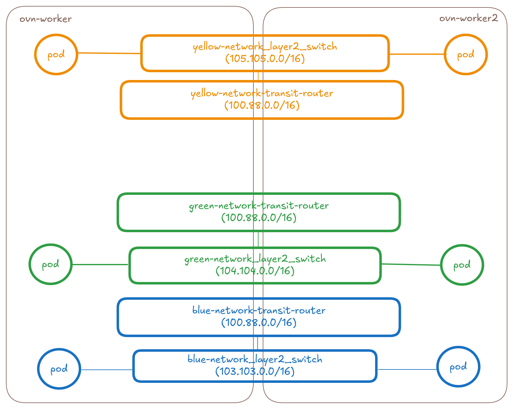
Add a new transit router between the transit routers of the networks
When the ClusterNetworkConnect CR gets created selecting these three
networks, the controller will make the following changes to the topology:
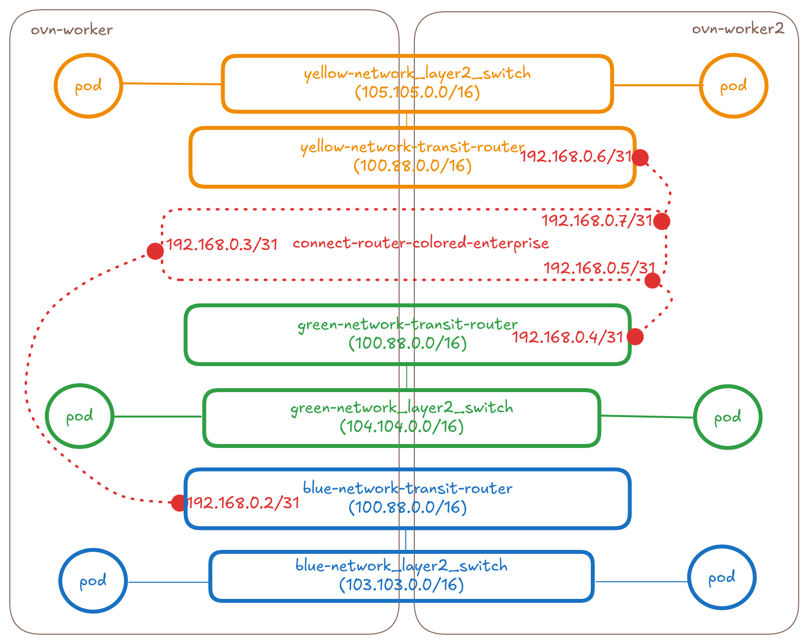
* Create a distributed connect-router-colored-enterprise (basically a
transit-router type in OVN used for interconnection). However note that
for pure layer2 network connections, we don't actually need a transit
router since there won't be any remote ports we need to create for
layer2 unlike in case of layer3. When we go from a pure layer2 to mixed
type connections we will need the remote ports (see the next section).
* Connect the connect-router-colored-enterprise to the transit-router’s
of the blue, green and yellow networks using patch ports and
tunnelkeys. In case of Layer2, we will have N links where N is the
number of networks.
* The port's will have IPs allocated from within the connectSubnets
value provided on the CR. For connecting N networks on M nodes we
would need 2×N IPs from the connectSubnets. See the controller
design section for more details.
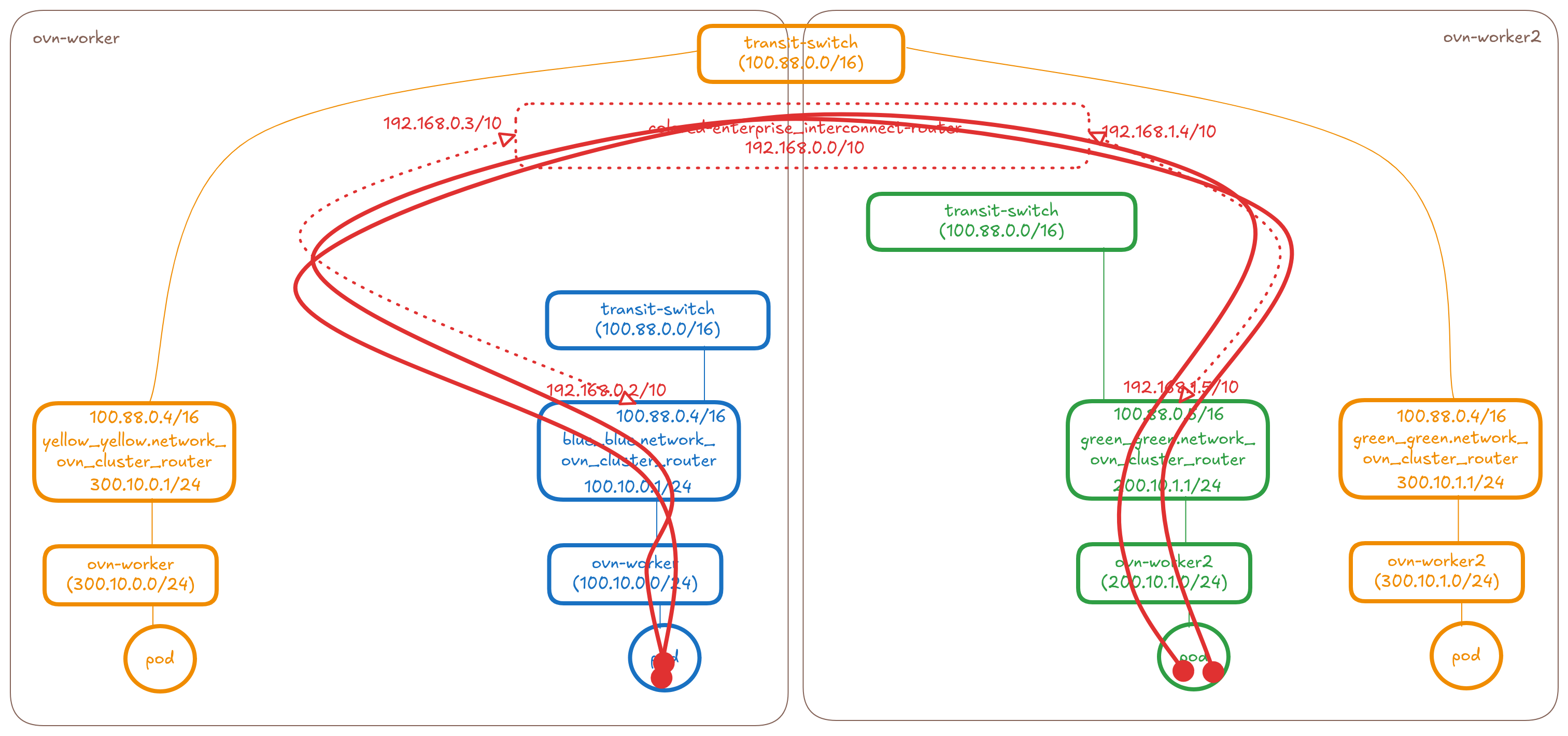
Connecting mixed type (layer3 and/or layer2) networks together
The below diagram shows the overlay part of the OVN Topology that OVN-Kubernetes creates for 3 UDN networks (blue(l3), green(l3) and yellow(l2)) across two nodes.
Add a new transit router between the ovn_cluster_router's and transit-routers of the networks
When the ClusterNetworkConnect CR gets created selecting these three
networks, the controller will make the following changes to the topology:
* Create a distributed connect-router-colored-enterprise (basically
a transit-router type in OVN used for interconnection). Remote ports
will be used only in layer3 type interconnection and not in layer2.
* Connect the connect-router-colored-enterprise to the
transit-router of the yellow network and ovn_cluster_router's of the
blue and green networks on each node using patch ports and tunnelkeys.
In case of mixed connection type, we will have N_L3×M+N_L2 links where
N_L3 is the number of Layer3 networks and N_L2 is the number of Layer2
networks
* The port's will have IPs allocated from within the connectSubnets
value provided on the CR. For connecting N_L3 and N_L2 networks on M nodes
we would need 2×(N_L3×M+N_L2) IPs from the connectSubnets. See the
controller design section for more details.
Pods
In order to ensure pods in different connected networks can talk to each other we will need to add appropriate routes on the routers.
- Create policies on each connected network's
ovn_cluster_router(L3) ortransit-router(L2) that steers the traffic towards the other networks' subnet to theconnect-router. - On the interconect
connect-routerwe will add specific per network-node subnet routes that steers the traffic to the correct node.
Layer3
These routes will look like this in the L3 blue, green, yellow sample topology:
- Add logical router policies to
blue_blue.network_ovn_cluster_routerthat steers traffic towards the green and yellow UDN's subnet to connect router on all nodes - Add logical router policies to
green_green.network_ovn_cluster_routerthat steers traffic towards the blue and yellow UDN's subnet to connect router on all nodes - Add logical router policies to
yellow_yellow.network_ovn_cluster_routerthat steers traffic towards the blue and green UDN's subnet to connect router on all nodes - On the
connect-router-colored-enterpriseadd routes to specific node subnet slices of the blue, green and yellow ovn_cluster_routers on the respective nodes.
sh-5.2# ovn-nbctl lr-policy-list green_green.network_ovn_cluster_router
Routing Policies
      9001 inport == "rtos-green_green.network_ovn-worker" && ip4.dst == 103.103.0.0/16         reroute              192.168.0.11
      9001 inport == "rtos-green_green.network_ovn-worker" && ip4.dst == 105.105.0.0/16         reroute              192.168.0.11
---
sh-5.2# ovn-nbctl lr-policy-list blue_blue.network_ovn_cluster_router
Routing Policies
      9001 inport == "rtos-blue_blue.network_ovn-worker" && ip4.dst == 104.104.0.0/16         reroute               192.168.0.7
      9001 inport == "rtos-blue_blue.network_ovn-worker" && ip4.dst == 105.105.0.0/16         reroute               192.168.0.7
---
sh-5.2# ovn-nbctl lr-policy-list yellow_yellow.network_ovn_cluster_router
Routing Policies
      9001 inport == "rtos-yellow_yellow.network_ovn-worker" && ip4.dst == 103.103.0.0/16         reroute               192.168.0.9
      9001 inport == "rtos-yellow_yellow.network_ovn-worker" && ip4.dst == 104.104.0.0/16         reroute               192.168.0.9
---
sh-5.2# ovn-nbctl lr-route-list connect-router-colored-enterprise
IPv4 Routes
Route Table <main>:
           103.103.0.0/24              192.168.0.12 dst-ip
           103.103.1.0/24               192.168.0.0 dst-ip
           103.103.2.0/24               192.168.0.6 dst-ip
           104.104.0.0/24               192.168.0.4 dst-ip
           104.104.1.0/24              192.168.0.10 dst-ip
           104.104.2.0/24              192.168.0.16 dst-ip
           105.105.0.0/24              192.168.0.14 dst-ip
           105.105.1.0/24               192.168.0.2 dst-ip
           105.105.2.0/24               192.168.0.8 dst-ip
Layer2
These routes will look like this in the L3 blue, green, yellow sample topology:
- Add logical router policies to
blue_blue.network_transit_routerthat steers traffic towards the green and yellow UDN's subnet to connect router on all nodes - Add logical router policies to
green_green.network_transit_routerthat steers traffic towards the blue and yellow UDN's subnet to connect router on all nodes - Add logical router policies to
yellow_yellow.network_transit_routerthat steers traffic towards the blue and green UDN's subnet to connect router on all nodes - On the
connect-router-colored-enterpriseadd routes to specific node subnet slices of the blue, green and yellow transit_routers. We don't need per-node routes like with layer3, since transit router is distributed across all nodes and layer2 is a flat network
sh-5.2# ovn-nbctl lr-policy-list green_green.network_transit_router
Routing Policies
      9001 inport == "trtos-green_green.network_ovn_layer2_switch" && ip4.dst == 103.103.0.0/16         reroute               192.168.0.7
      9001 inport == "trtos-green_green.network_ovn_layer2_switch" && ip4.dst == 105.105.0.0/16         reroute               192.168.0.7
---
sh-5.2# ovn-nbctl lr-policy-list blue_blue.network_transit_router
Routing Policies
      9001 inport == "trtos-blue_blue.network_ovn_layer2_switch" && ip4.dst == 104.104.0.0/16         reroute              192.168.0.11
      9001 inport == "trtos-blue_blue.network_ovn_layer2_switch" && ip4.dst == 105.105.0.0/16         reroute              192.168.0.11
---
sh-5.2# ovn-nbctl lr-policy-list yellow_yellow.network_transit_router
Routing Policies
      9001 inport == "trtos-yellow_yellow.network_ovn_layer2_switch" && ip4.dst == 103.103.0.0/16         reroute               192.168.0.9
      9001 inport == "trtos-yellow_yellow.network_ovn_layer2_switch" && ip4.dst == 104.104.0.0/16         reroute               192.168.0.9
---
sh-5.2# ovn-nbctl lr-route-list connect-router-colored-enterprise
IPv4 Routes
Route Table <main>:
           103.103.0.0/16               192.168.0.4 dst-ip
           104.104.0.0/16               192.168.0.0 dst-ip
           105.105.0.0/16               192.168.0.2 dst-ip
Mixed
These routes will look like this in the mixed blue, green, yellow sample topology:
- Add logical router policies to
blue_blue.network_ovn_cluster_routerthat steers traffic towards the green and yellow UDN's subnet to connect router on all nodes - Add logical router policies to
green_green.network_ovn_cluster_routerthat steers traffic towards the blue and yellow UDN's subnet to connect router on all nodes - Add logical router policies to
yellow_yellow.network_transit_routerthat steers traffic towards the blue and green UDN's subnet to connect router on all nodes - On the
connect-router-colored-enterpriseadd routes to specific node subnet slices of the blue, green ovn_cluster_router on the respective nodes and 1 global route to the distributed yellow transit_router
sh-5.2# ovn-nbctl lr-policy-list blue_blue.network_ovn_cluster_router
Routing Policies
      9001 inport == "rtos-blue_blue.network_ovn-worker" && ip4.dst == 104.104.0.0/16         reroute              192.168.0.17
      9001 inport == "rtos-blue_blue.network_ovn-worker" && ip4.dst == 105.105.0.0/16         reroute              192.168.0.17
---
sh-5.2# ovn-nbctl lr-policy-list green_green.network_ovn_cluster_router
Routing Policies
      9001 inport == "rtos-green_green.network_ovn-worker" && ip4.dst == 103.103.0.0/16         reroute              192.168.0.13
      9001 inport == "rtos-green_green.network_ovn-worker" && ip4.dst == 105.105.0.0/16         reroute              192.168.0.13
---
sh-5.2# ovn-nbctl lr-policy-list yellow_yellow.network_transit_router
Routing Policies
      9001 inport == "trtos-yellow_yellow.network_ovn_layer2_switch" && ip4.dst == 103.103.0.0/16         reroute              192.168.0.15
      9001 inport == "trtos-yellow_yellow.network_ovn_layer2_switch" && ip4.dst == 104.104.0.0/16         reroute              192.168.0.15
---
sh-5.2# ovn-nbctl lr-route-list connect-router-colored-enterprise
IPv4 Routes
Route Table <main>:
           103.103.0.0/24               192.168.0.12 dst-ip
           103.103.1.0/24               192.168.0.10 dst-ip
           103.103.2.0/24               192.168.0.4 dst-ip
           104.104.0.0/24               192.168.0.6 dst-ip
           104.104.1.0/24               192.168.0.0 dst-ip
           104.104.2.0/24               192.168.0.8 dst-ip
           105.105.0.0/16               192.168.0.2 dst-ip
Overlapping Subnets
Direct pod to pod connectivity of two networks is not supported in phase1. Conflict overlap detection and notification via API must be implemented.
Services
Case1: ServiceNetwork is not set
no-op. Services connectivity is not supported across connected UDNs.
Case2: ServiceNetwork and PodNetwork are set
If the ServiceNetwork is explicitly requested, then
it means the end user wants the services of both networks to be
connected. In this case, we need to modify the services controller to
program the OVN load balancers on the local network switches also for
connected networks so that once the DNAT to the backend happens it takes
the same path as the policies and routes outlined in the Pods section.
Example, if we have blue and green clusterIP services:
$ k get svc -n blue
NAME           TYPE        CLUSTER-IP      EXTERNAL-IP   PORT(S)   AGE
service-blue   ClusterIP   10.96.210.158   <none>        80/TCP    57m
k get svc -n green
NAME            TYPE        CLUSTER-IP    EXTERNAL-IP   PORT(S)   AGE
service-green   ClusterIP   10.96.69.71   <none>        80/TCP    58m
k get endpointslice -n blue
NAME                 ADDRESSTYPE   PORTS   ENDPOINTS                 AGE
service-blue-czpg2   IPv4          8080    103.103.0.5,103.103.2.5   58m
service-blue-l26v9   IPv4          8080    10.244.2.3,10.244.1.6     58m
k get endpointslice -n green
NAME                  ADDRESSTYPE   PORTS   ENDPOINTS                 AGE
service-green-ngrrc   IPv4          8080    10.244.2.5,10.244.1.8     58m
service-green-rs2wv   IPv4          8080    104.104.2.4,104.104.1.4   58m
---
sh-5.2# ovn-nbctl ls-lb-list green_green.network_ovn-worker
UUID                                    LB                  PROTO      VIP               IPs
ab3397dd-6c4f-41bd-9239-60c73c25aaee    green_green.netw    tcp        10.96.69.71:80    104.104.1.4:8080,104.104.2.4:8080
sh-5.2# ovn-nbctl ls-lb-list blue_blue.network_ovn-worker
UUID                                    LB                  PROTO      VIP                 IPs
04aa1e0b-bfec-4270-94f0-4b6d511b63a3    blue_blue.networ    tcp        10.96.210.158:80    103.103.0.5:8080,103.103.2.5:8080
We need the controller to also add ab3397dd-6c4f-41bd-9239-60c73c25aaee
to blue_blue.network_ovn-worker and 04aa1e0b-bfec-4270-94f0-4b6d511b63a3
to green_green.network_ovn-worker for the blue pods to be able to
talk to green service and vice versa. The switches will DNAT the traffic
and the policies and routes we added in the Pods section will take
care of routing the DNAT-ed traffic to the correct network.
sh-5.2# ovn-nbctl ls-lb-add blue_blue.network_ovn-worker ab3397dd-6c4f-41bd-9239-60c73c25aaee
sh-5.2# ovn-nbctl ls-lb-add green_green.network_ovn-worker 04aa1e0b-bfec-4270-94f0-4b6d511b63a3
sh-5.2# ovn-nbctl ls-lb-list blue_blue.network_ovn-worker
UUID                                    LB                  PROTO      VIP                 IPs
04aa1e0b-bfec-4270-94f0-4b6d511b63a3    blue_blue.networ    tcp        10.96.210.158:80    103.103.0.5:8080,103.103.2.5:8080
ab3397dd-6c4f-41bd-9239-60c73c25aaee    green_green.netw    tcp        10.96.69.71:80      104.104.1.4:8080,104.104.2.4:8080
sh-5.2# ovn-nbctl ls-lb-list green_green.network_ovn-worker
UUID                                    LB                  PROTO      VIP                 IPs
04aa1e0b-bfec-4270-94f0-4b6d511b63a3    blue_blue.networ    tcp        10.96.210.158:80    103.103.0.5:8080,103.103.2.5:8080
ab3397dd-6c4f-41bd-9239-60c73c25aaee    green_green.netw    tcp        10.96.69.71:80      104.104.1.4:8080,104.104.2.4:8080
Case3: ServiceNetwork is set and PodNetwork is not set
This means user is asking for partial connectivity between UDNs through serviceCIDRs. They don't want direct connectivity between all their applications.
We will use ACLs in Tier0 to allow traffic to service CIDR
and drop all connected_udn_subnet pod traffic. These ACLs
will be added on the local node switches for layer3 networks
and the distributed flat switch for layer2 networks.
They are applied in the from-lport direction for traffic
originating from the pod's ports.
_uuid               : e88434bf-70c2-4853-810e-ecb2a64aaaa7
action              : pass
direction           : from-lport
external_ids        : {}
label               : 0
log                 : false
match               : "ip4.dst==10.96.0.0/16"
meter               : []
name                : []
options             : {}
priority            : 5000
sample_est          : []
sample_new          : []
severity            : []
tier                : 0
---
sh-5.2# ovn-nbctl list address-set connected_udn_subnets
_uuid               : d340f83e-0adb-4f8c-9196-1e36ddcda7e9
addresses           : ["103.103.0.0/16", "104.104.0.0/16", "105.105.0.0/16"]
external_ids        : {}
name                : connected_udn_subnets
---
_uuid               : cfe7b1cd-25cc-4f4f-8d15-f7b978ef43a1
action              : drop
direction           : from-lport
external_ids        : {}
label               : 0
log                 : false
match               : "ip4.src==$connected_udn_subnets && ip4.dst==$connected_udn_subnets && ct.new"
meter               : []
name                : []
options             : {}
priority            : 4950
sample_est          : []
sample_new          : []
severity            : []
tier                : 0
---
sh-5.2# ovn-nbctl acl-list green_green.network_ovn-worker2
from-lport  5000 (ip4.dst==10.96.0.0/16) pass --> new ACL in tier0
from-lport  4999 (ip4.src==$connected_udn_subnets && ip4.dst==$connected_udn_subnets && ct.new) drop --> new ACL in tier0
  to-lport  1001 (ip4.src==104.104.0.2) allow-related --> tier2 (allow healthchecks from kubelet)
---
sh-5.2# ovn-nbctl acl-list blue_blue.network_ovn-worker2
from-lport  5000 (ip4.dst==10.96.0.0/16) pass --> new ACL in tier0
from-lport  4999 (ip4.src==$connected_udn_subnets && ip4.dst==$connected_udn_subnets && ct.new) drop --> new ACL in tier 0
  to-lport  1001 (ip4.src==103.103.1.2) allow-related --> tier2 (allow healthchecks from kubelet)
apply-after-lb=false so the service
DNAT will happen after the ACLs are applied. Similarly for the response
the unDNAT will happen before ACLs for the replies. This guarantees traffic
destined directly to the pods in other connected networks will be
dropped but if its destined to a clusterIP service, then after the
ACL stage, we will hit the load balancing stage in the pipeline
where the DNAT to backend IP will happen. Remaining workflow is same
as the Pods section where the traffic will be routed to the
connect-router.
These ACLs take precedence over other ACL features (ANPs, NetPols) and that is the defined behaviour since if full connectivity for PodNetwork is not requested, then network policies are a no-op and need not be honored for the cross-network connection case.
NOTE: Since we always have a allow-related ACL on our switches:
to-lport 1001 (ip4.src==103.103.1.2) allow-related
ct.new match in the drop ACL
since ct session should automatically be maintained by OVN and
replies shouldn't be dropped. However while doing the PoC I don't
see this working as expected and when I remove the ct.new
match, drop seems to be happening that too at an unexpected
places in the pipeline which needs more investigation. During
implementation phase, if we fix that behaviour then we can remove
the ct.new match from the ACL.
Traffic Path:
Onward Traffic Flow:
┌──────┐     ┌──────────────┐     ┌─────────────┐     ┌───────────────┐     ┌─────────────┐     ┌──────────────┐     ┌──────┐
│ podA │───▶│ UDNA switch  │───▶│ UDNA router │───▶│ connect router│───▶│ UDNB router │───▶│ UDNB switch  │───▶│ podB │
└──────┘     └──────────────┘     └─────────────┘     └───────────────┘     └─────────────┘     └──────────────┘     └──────┘
              (DNAT to podB)         (LRPs)               (LRSRs)              (LRSR)

Response Traffic Flow:
┌──────┐     ┌──────────────┐     ┌─────────────┐     ┌───────────────┐     ┌─────────────┐     ┌──────────────┐     ┌──────┐
│ podA │◀───│ UDNA switch  │◀───│ UDNA router │◀───│ connect router│◀───│ UDNB router │◀───│ UDNB switch  │◀───│ podB │
└──────┘     └──────────────┘     └─────────────┘     └───────────────┘     └─────────────┘     └──────────────┘     └──────┘
              (unSNAT to CIP)        (LRSR)                 (LRSR)             (LRP)
Overlapping Subnets
We will not support connecting networks via services that have overlapping subnets in the first iteration. Proper user feedback indicating an error will be provided in case users try to connect networks with overlapping subnets.
Network Policies and Admin Network Policies
If PodNetwork is set, then Network Policies
and AdminNetworkPolicies (when they get supported on UDNs)
that are created in the networks that are part of
ClusterNetworkConnect API will have peers that span across all
connect networks. So the scope of policies will be within all
connected networks.
If PodNetwork is not set, then policies won't
apply across networks since there is no need to do so.
Controller Design / Changes to Components
Cluster Manager
A new network-connect-controller will be created that watches the
ClusterNetworkConnect objects and does the following:
1) It is responsible to allocate a range for each network:
* It get's the connectSubnets value from the CNC and allocates
a /networkPrefix subnet for each layer3 connected network.
If its a layer2 type network, then allocator gives out a
/networkPrefix subnet and then from that gives out a /31 or
/127 slice subnet for each layer2 network. So until that
/networkPrefix subnet is exhausted, all subsequent layer2
networks will use that range.
* These values are annotated on the ClusterNetworkConnect
CRD for it to be then consumed on the ovnkube-controller side.
Sample:
k8s.ovn.org/network-subnets: {
  layer3_<network1-id>: {"ipv4": "192.168.0.0/24", "ipv6":"fd01:0:0:0::/64"},
  layer3_<network2-id>: {"ipv4": "192.168.1.0/24", "ipv6": "fd01:0:0:1::/64"},
  layer3_<network5-id>: {"ipv4": "192.168.2.0/24", "ipv6": "fd01:0:0:2::/64"},
  layer3_<network12-id>: {"ipv4": "192.168.3.0/24", "ipv6": "fd01:0:0:3::/64"},
  layer2_<network40-id>: {"ipv4": "192.168.4.0/31", "ipv6": "fd01:0:0:4::/127"},
  layer2_<network103-id>: {"ipv4": "192.168.4.2/31", "ipv6": "fd01:0:0:4::2/127"},
  layer3_<network15-id>: {"ipv4": "192.168.5.0/24", "ipv6": "fd01:0:0:5::/64"},
  layer2_<network2000-id>: {"ipv4": "192.168.4.4/31", "ipv6": "fd01:0:0:4::4/127"},
  ...
}
N_L3*M+N_L2 subnets and 2x(N_L3*M+N_L2) IPs.
However in this method, we plan to let CM give a slice for each
layer3 connected network based on networkPrefix and each
layer2 connected network a /31- so that means we
are going to consume N_L3*M+N_L2 subnets and 2x(N_L3*M+N_L2) IPs
where M is maximum nodes in your cluster. Users need to be careful because
this networkPrefix can limit the maximum number of nodes in your
cluster. On the node side from this networkPrefix, we will give out
a /31 for each node. For layer3 networks, its possible the node-ids
are not contiguous so we will loose out on a few IPs in the middle sparsely.
This method was chosen so that we don't need to annotate a lot of
N*M values on our annotation which will make it bloat a lot
from performance and scale perspective.
2) It is responsible for allocating the global tunnel key for each
connect-router:
* It will use the same instance of global TunnelKeysAllocator
in cluster manager that already allocates the tunnel keys for
existing Layer2 transit routers. This allocator already
preserves the first 4096 IDs which are used as tunnel-keys
for Layer3 and Layer2 transit switches (derived from the networkID
that is allocated by the networkID allocator).
TunnelKeysAllocator will then allocate the new ones for the
connect router dynamically. This ensures we don't reuse
already allocated networkIDs. For each connect API that will
create a connect router, we will need 1 tunnel key per router.
* This value is annotated on the ClusterNetworkConnect
CRD for it to be then consumed on the ovnkube-controller side.
Sample:
k8s.ovn.org/connect-router-tunnel-key: '50000'
ovnkube-controllers in different zones.
This controller also needs to watch for NADs to accommodate adds, updates and deletes for the network-subnet.
OVN-Kubernetes Controller
A new network-connect-controller will be created that watches the
ClusterNetworkConnect objects and does the following:
1) Based on the network selectors, creates the
necessary network topology changes mentioned
in the above section:
* Creates the connect-router
* Creates the ports connecting each Layer3 ovn_cluster_router and
each Layer2 transit-router to the connect-router
* Adds the necessary logical router policies on each network router
* Adds the necessary logical router static routes on the connect-router
2) Reads the k8s.ovn.org/network-subnets
annotation set by the cluster manager on CNC and allocates
a /31 point to point subnet for each layer3 node-network's router port link
and uses the IPs from the /31 to create the ports. For layer2 we only
need one /31 instead of per node /31's which is already allocated by
CM. This allocator will be a static allocator util that deterministically
always picks the same /31 for every node-id. Example:
 worker-1 (node-id=0) → 10.2.0.0/31 (10.2.0.0 + 10.2.0.1)
 worker-2 (node-id=1) → 10.2.0.2/31 (10.2.0.2 + 10.2.0.3)
 worker-3 (node-id=2) → 10.2.0.4/31 (10.2.0.4 + 10.2.0.5)
 worker-4 (node-id=5) → 10.2.0.10/31 (10.2.0.10 + 10.2.0.11)
generator.GenerateP2PSubnet(nodeID * 2).
For layer2 we will just use the annotation value directly.
3) Reads the k8s.ovn.org/connect-router-tunnel-key and uses
the tunnel key to create the connect-router
4) Within each connect-router, we would need N_L3*M tunnel keys to
connect N_L3 Layer3 networks on M nodes and N_L2 tunnel keys to connect
N_L2 Layer2 networks on M nodes. So total of N_L3*M+N_L2 keys.
* This will be done statically based on subnets allocated out for each
node-network pair for layer3 networks and for each layer2 network. See the
Deterministic Static TunnelID Allocator approach mentioned below for details.
5) Creates the pass and drop ACLs if only partial service connectivity
is requested
6) If ServiceNetwork is set, then once the services
controller of each network creates the load balancers (retries till
its created), this controller will also attach those load balancers
to the switches of the connected networks. This way, no changes are
required to existing services controller. However this means network-connect
controller will need to watch for endpointslice and services
objects.
This controller watches for CNCs, NADs, Services, Endpointslices and Nodes to react to events. It will be a level driven controller.
Deterministic Static Tunnel ID Allocation Algorithm used by ovnkube-controller
The tunnel IDs for connect-router ports are allocated deterministically based on the existing subnet allocations. This ensures consistency across all ovnkube-controller instances without requiring coordination.
Algorithm Overview
- Calculate maxNodes:
maxNodes = 2^(32 - NetworkPrefix) - For NetworkPrefix=24: maxNodes=128
-
For NetworkPrefix=25: maxNodes=64
-
Calculate network index: Based on the subnet's position in the NetworkPrefix range
-
Allocate tunnel keys:
- Layer3 networks:
tunnelKey = networkIndex * maxNodes + nodeID + 1 - Layer2 networks:
tunnelKey = networkIndex * maxNodes + subIndex + 1
Example Allocation
Given NetworkPrefix=24 (maxNodes=128):
| Network | Subnet | Type | Index | Tunnel Key Range |
|---|---|---|---|---|
| network1 | 192.168.0.0/24 | Layer3 | 0 | [1, 128] |
| network2 | 192.168.1.0/24 | Layer3 | 1 | [129, 256] |
| network5 | 192.168.2.0/24 | Layer3 | 2 | [257, 384] |
| network12 | 192.168.3.0/24 | Layer3 | 3 | [385, 512] |
| network40 | 192.168.4.0/31 | Layer2 | 4 | [513] |
| network103 | 192.168.4.2/31 | Layer2 | 4 | [514] |
| network15 | 192.168.5.0/24 | Layer3 | 5 | [641, 768] |
Scale Limitations
The maximum number of connectable networks is limited by:
- Tunnel key limit: 32767 (reserved: 0 since 0 is invalid tunnelKey)
- Available keys: 32766
- Max networks: 32766 / maxNodes
| NetworkPrefix | maxNodes | Max Networks |
|---|---|---|
| /24 | 128 | 255 |
| /25 | 64 | 511 |
| /26 | 32 | 1023 |
Cross Feature Interaction
Connecting Advertised UDNs
The ACLs that are added to block traffic routing between the two UDNs in strict mode will be removed so that traffic can flow between networks once connected.
A side caveat here is instead of the edge router doing the routing, OVN-Kubernetes itself will take care of routing the traffic. If that is not desired, then users should stick with loose isolation mode using BGP and not use this feature.
Connecting UDNs with no overlay mode
This feature will not be supported if overlay tunnel encapsulation is turned off. Cluster Manager will perform the necessary steps to validate and emit a message to the end user reporting an error if they tried to connect UDNs when overlay is turned off.
Testing Details
- Unit Testing details - All code modules will have necessary unit tests
- E2E Testing details - Entire feature will have E2E and Integration testing
- API Testing details - CEL rules and API validation will have its own apply test suite
- Scale Testing details - Bare minimum set of scale testing will be done for this feature although we probably need to fix UDN Scale first
- Cross Feature Testing details - coverage for interaction with other features like BGP and no-overlay mode
Documentation Details
- User guide will be updated for the feature on ovn-kubernetes.io website
- Blog posts and easy to get started guides will be done on ovn-kubernetes.io website
- Developer docs whereever possible will be added
Risks, Known Limitations and Mitigations
Scale and Performance
- Adding a /16 route to each router for each connected peer network and then adding /24 routes for each node-network combo on the transit router has scale implications specially on clusters with large nodes. A cluster with 500 nodes and 500 networks will end up with 250000 routes on each transit router distributed half on the node.
- In future there is a requirement to not create OVN constructs for UDNs on those nodes where we know there won't be pod's scheduled. This is to optimize resource consumption on large scale clusters with 1000 nodes where only 10 nodes are going to host UDNs. Whatever topology we pick here must work for that future enhancement as changing topologies is not really encouraged. See Dynamic UDN Node Allocation for more details.
- The annotations we add to the CNC has cost of marshal and unmarshal at each ovnkube-controller
OVN Kubernetes Version Skew
Targeting release 1.2
Alternatives
Using BGP and RouterAdvertisement API
If admin wants to connect two UDNs together then they can simply expose the two UDNs using RouterAdvertisement CR and the router acting as gateway outside the cluster will learn the pod subnet routes from both these UDNs thereby acting as the router and being able to connect pods together. Today we add ACLs, but those could be removed to accommodate the connectivity.
Pros
- No need for a new API to connect UDNs together
- Implementation changes are also almost nil
Cons
- Some users might want to use BGP and UDNs only for the pods to be directly accessible from external destinations and within the cluster they might still want to respect segmentation - this is not possible if we declare exposing UDNs subnets using BGP also means they are now connected together. So basically the current API didn't account for BGP to solve connecting UDNs problem.
- Some users might not want to use BGP at all because that makes assumptions on having the right fabric at the cluster infrastructure layer like presence of FRR-K8s which might not be the case always - then how can they connect their UDNs together? Solution needs to be OVN-native where-ever possible.
- Users cannot ask for partial v/s full connectivity across these UDNs
- example allow only services not pods.
- Hardware offload not possible since traffic is not curtailed only to the OVS stack
Using alternative connection ideas on OVN topology level
See discarded-alternatives.md for details on alternative topology connection ideas that were considered but discarded.
Using NodeNetwork CR instead of Annotations on ClusterNetworkConnect API
NOTE: Having the NodeNetwork CRD as an internal data storage API might
be more ideal to store the above information internally as this needs to
be persisted into etcd on reboots. It will simplify the annotations and
also help with scale since there are known issues around patching of
annotation and waiting for reading and unmarshalling the annotation
impacts scale. But this theory is not proven yet. During discussions we
concluded it wouldn't be faster because the NetworkConnectController
would be the only one watching for these CRs and it will need to process
all the data and networks anyway.
Have ClusterManager give out point to point subnet slices
Initial design had:
    k8s.ovn.org/node-network-subnets: {
      layer3_<network1-id>_<node1name>: 192.168.0.0/31,
      layer3_<network1-id>_<node2name>: 192.168.0.2/31,
      layer3_<network1-id>_<node3name>: 192.168.0.4/31,
      layer3_<network2-id>_<node1name>: 192.168.0.6/31,
      layer3_<network2-id>_<node2name>: 192.168.0.8/31,
      layer3_<network3-id>_<node3name>: 192.168.0.10/31,
      layer2_<network1-id>: 192.168.0.12/31,
      layer2_<network2-id>: 192.168.0.14/31,
      ...
    }
N_L3*M+N_L2 subnets and 2x(N_L3*M+N_L2) IPs. This had the advantage
of the ranges being contiguous and no wasted IPs in connectSubnets range
compared to the solution we have today.
Adding load balancers on transit connect routers for services
Alternative Idea2: Instead of doing the DNAT at the network switches, we could add the load balancers to the connect router.
If ServiceNetwork is set, then we add routes for each
clusterIP that belongs to the other connected networks
to be routed to the connect-router or a ClusterIP CIDR route.
We would need to then either host all load balancers for all connected
networks on the connect-router OR we would need to route the clusterIP to
any random node-network pair belonging to the destination network
where the DNAT and reroute would happen but that's complicated.
If we go with adding load balancers to the connect router, then
traffic path looks like this:
Forward Path (podA -> podB):
┌──────┐     ┌──────────────┐     ┌─────────────┐     ┌───────────────┐     ┌─────────────┐     ┌──────────────┐     ┌──────┐
│ podA │───▶│ UDNA switch  │───▶│ UDNA router │───▶│ connect router│───▶│ UDNB router │───▶│ UDNB switch  │───▶│ podB │
└──────┘     └──────────────┘     └─────────────┘     └───────────────┘     └─────────────┘     └──────────────┘     └──────┘
                                      (LRP)          (DNAT to podB +        (LRSR)
                                                           LRSR)

Return Path (podB -> podA):
┌──────┐     ┌──────────────┐     ┌─────────────┐     ┌───────────────┐     ┌─────────────┐     ┌──────────────┐     ┌──────┐
│ podA │◀───│ UDNA switch  │◀───│ UDNA router │◀───│ connect router│◀───│ UDNB router │◀───│ UDNB switch  │◀───│ podB │
└──────┘     └──────────────┘     └─────────────┘     └───────────────┘     └─────────────┘     └──────────────┘     └──────┘
                                      (LRSR)        (unSNAT to cip +      (need LRPs
                                                           LRSR)          for reply)
So in the end we'd need CIP routes and pod subnet routes + add the load balancers to connect router and also add ACLs to drop direct traffic towards pod subnets but only allow replies for service traffic for idea2 v/s for idea1 we don't need the CIP routes an rest remains the same except load balancers are added to the switches instead of routers. However, idea2 won't work because transit routers have same limitations as regular distributed routers in OVN when it comes to connection tracking. Given the Layer2 transit router to Connect router is a distributed port, traffic coming from the layer2 switch -> layer2 router -> connect router cannot be load balanced.
Dependencies
- This enhancement depends on the new Layer2 topology changes.