Multi-VTEP
Introduction
When a K8s cluster has multiple networks and K8s nodes have multiple SR-IOV network adapters to provide different overlaying virtual networks over the physical networks, multiple VTEP(Virtual Tunnel EndPoint) devices are required for encapsulating and de-encapsulating the network traffic from/to virtual networks. The challenge is in deciding which VTEP to use to send/receive the packets to/from the wire. This feature instructs OVN to use the appropriate VTEP IP as the source or destination IP for east-west traffic.
Motivation
For applications with network traffic that can be categorized by purpose and are sensitive to network latency, it is advantageous to use multiple NICs designated for different purposes. This enhances the performance, security, and flexibility of the network. Additionally, with network adapters that support SR-IOV, traffic can be offloaded to hardware, further reducing network latency and decreasing host CPU usage.
User-Stories/Use-Cases
Consider a cloud environment providing online video streaming, where each node is equipped with three NICs. One NIC could be dedicated to management traffic, another to video streaming traffic, and the third to storage. In this setup, each NIC would have its own VTEP IP. This configuration ensures that overlay traffic from a Pod’s VF is steered through the specific NIC associated with that VF. For example, streaming traffic must be routed exclusively through the second NIC, optimizing network performance and traffic segregation.
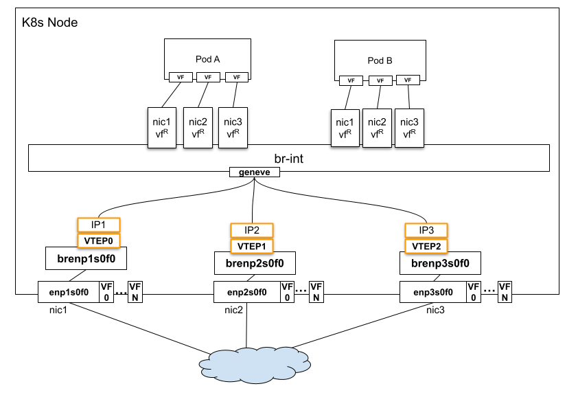
- vfR is VF representor.
How to enable this feature on an OVN-Kubernetes cluster?
On OVN-Kubernetes side, no additional configuration required to enable this feature.
This feature depends on a specific underlay network setup; it cannot be turned on without an adequate underlay network configuration.
Always check the dependencies on the Requirements page
Implementation Details
This feature requires an OVN version newer than v24.03.2.
When the source and destination are overlay IPs, the packets need to be encapsulated and sent through a tunnel. When there are multiple NICs used for tunneling traffic, each with a different VTEP IP, OVN needs to select the right tunnel endpoint to send the traffic, based on the below criteria:
- The tunnel/NIC selection should be based on the source & destination interface of the traffic, which should be aligned with the VF selection specified by ovn-kubernetes.
- The source tunnel IP should be selected according to the source interface of the packet.
- The destination tunnel IP should be selected according to the destination interface of the packet.
- If an interface is not assigned a VTEP, traffic to/from the interface can choose any VTEP of the host.
- For BUM(broadcast, unknown-unicast, and multicast traffic) traffic, it is ok to select any VTEP.
OVN Constructs created in the databases
OVN Sourthbound Database: * Port_Binding:encap - Populated by ovn-controller according to VIF interface’s external_ids:ovn-encap-ip. * Encap:IP - The IP in the corresponding Encap record will be used as the VTEP IP.
OVS Database on chassis:
* Each Chassis may have multiple Encaps, determined by
open_vswitch:external_ids:ovn-encap-ip which is a comma separated
string of IPs.
* Each VIF interface (if needs to be assigned to a particular VTEP)
will have external_ids:ovn-encap-ip, which must be one of the IPs
configured in open_vswitch:external_ids:ovn-encap-ip of the chassis.
* A option open_vswitch:external_ids:ovn-pf-encap-ip-mapping is
added to define the mapping between PF interface name and its VTEP IP.
OVN-Kubernetes Implementation Details
To support this feature, the VTEP interfaces must be configured in advance. This can be accomplished using a system network management tool, such as Network Manager.
Assuming a node has 3 NICs and VTEP interfaces: | PF | VTEP | VTEP IP | | :------- | :---- | :----------- | | enp1s0f0 | vtep0 | 10.0.0.1/23 | | enp2s0f0 | vtep1 | 10.0.0.2/23 | | enp3s0f0 | vtep2 | 10.0.0.3/23 |
The VTEP interfaces on OVS bridges should be configured as below:
$ ovs-vsctl  show
e620a080-c761-44d0-adb3-203bb1df6d67
    Bridge brenp1s0f1
        ...
        Port vtep0
            tag: 25 # just an example VLAN-ID
            Interface vtep0
                type: internal
    Bridge brenp2s0f0
        ...
        Port vtep1
            tag: 25
            Interface vtep1
                type: internal
    Bridge brenp3s0f0
        ...
        Port vtep2
            tag: 25
            Interface vtep2
                type: internal
Below Open_vSwitch external_ids need to be configured in osvsdb:
- external_ids:ovn-encap-ip: set it to a list of vtep IPs, separated by
commas, in any order.
- external_ids:ovn-pf-encap-ip-mapping: set it to list of vtep-interface
to IP pairs separated by comma.
For example:
$ ovs-vsctl --timeout=15 --if-exists get Open_vSwitch . external_ids:ovn-encap-ip
"10.0.0.1,10.0.0.2,10.0.0.3"

$ ovs-vsctl --timeout=15 --if-exists get Open_vSwitch . external_ids:ovn-pf-encap-ip-mapping
"enp1s0f0:10.0.0.1,enp2s0f0:10.0.0.2,enp3s0f0:10.0.0.3"
external_ids:ovn-encap-ip settings, OVN creates 3 tunnel ports for
each encap-ip on remote node, that's, if remote node has 2 encap-ips in
external_ids:ovn-encap-ip, 6 tunnel ports will be created on the local node.
For example, if remote node only has one encap-ip "10.0.0.10", OVN creates
below tunnel ports on the local node:
$ ovs-vsctl  show
    Bridge br-int
        Port ovn0-5e3e5-0
            Interface ovn0-5e3e5-0
                type: geneve
                options: {csum="true", key=flow, local_ip="10.0.0.1", remote_ip="10.0.0.10", tos=inherit}
        Port ovn0-e815c-1
            Interface ovn0-e815c-1
                type: geneve
                options: {csum="true", key=flow, local_ip="10.0.0.2", remote_ip="10.0.0.10", tos=inherit}
        Port ovn-33f2e5-0
            Interface ovn-33f2e5-0
                type: geneve
                options: {csum="true", key=flow, local_ip="10.0.0.3", remote_ip="10.0.0.10", tos=inherit}
Ovn-controller programs physical flows that create mappings between
When ovnkube-node adding a Pod's network interfaces to OVS br-int during the Pod
creation, it identifies the corresponding PF interface for each VF interface, it
then looks up external_ids:ovn-pf-encap-ip-mapping to determine the encap IP,
which is subsequently assigned to the OVS Port's external_ids:ovn-encap-ip.
This encap IP will be utilized as the source IP in the tunnel header.
To steer outgoing traffic through the correct physical interface, the following source-based routing rules are required on K8s node:
$ ip rule list
...
6081:   from 10.0.0.1 lookup 6081 proto static
6082:   from 10.0.0.2 lookup 6082 proto static
6083:   from 10.0.0.3 lookup 6083 proto static

$ ip route list table 6081
10.0.0.0/23 dev vtep0 scope link
10.0.0.0/16 via 10.0.0.1 dev vtep0 proto static metric 804
$ ip route list table 6082
10.0.0.0/23 dev vtep1 scope link
10.0.0.0/16 via 10.0.0.1 dev vtep1 proto static metric 802
$ ip route list table 6083
10.0.0.0/23 dev vtep2 scope link
10.0.0.0/16 via 10.0.0.1 dev vtep2 proto static metric 806
Known Limitations
This feature only works with network adapters that support SR-IOV, e.g. NVIDIA CONNECTX-6 or NVIDIA BlueField-2 in NIC mode.